SODIUM CHLORATE PLANT
Technologies / Sodium Chlorate Plant
SODIUM CHLORATE PLANT
Modular Skid based Plant Built for chlorate production
SODIUM CHLORATE
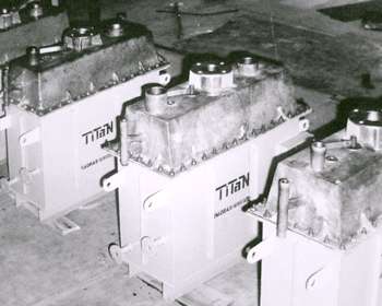
Noble Eco Systems’s Sodium chlorate manufacturing system consists of Electrolyzers, a reactor, a cooler, Crystallizer, Centrifuge, Dryer, Inter-connecting piping. When direct current is applied, the hydrogen gas is evolved at the Cathode, which displaces liquor and reduces the specific gravity of the electrolyte in the electrolyser and the outlet piping. The differential specific gravity between the liquor in the electrolyser and that in the reactor creates a high rate of circulation. The circulation is through the cooler, into the bottom of each cell in the electrolyser, between the anodes and cathodes in the cells where electrolysis occur, up the riser pipes to the degasifier (where the hydrogen separates) and back to the top of the reactor. The heat produced in the electrolysers is removed by an external cooler, which maintains the electrolytic system at its optimum operating temperature. The reactor is designed to provide the retention time required for conversion of intermediate reaction products to sodium chlorate.The liquor from the reactor is treated to remove the sodium hypochlorite and then fed to the crystallization system. The crystallization system consists of a crystallizer, Vacuum equipment, a centrifuge and dryer. The crystallizer operates under vacuum conditions. In the vessel, water is flashed from hot incoming hypo-free chlorate liquor and crystal formation and growth takes place. The mother liquor is returned to the Electrolysers. The crystals are washed and dried to form the final product.
SODIUM CHLORATE MANUFACTURING PROCESS
The manufacturing process of Sodium chlorate involves the electrolysis of an acidified sodium chloride solution in a specially designed Electrolyser.First, raw brine is treated to remove impurities such as calcium and magnesium. Hydrochloric acid (HCl) is added to control the pH and improve efficiency. Sodium dichromate is used as a catalyst, to inhibit electrochemical side reactions and as a pH buffer.
MEMBRANE CELL PROCESS
The main process of manufacturing chlorine and caustic soda consists primary brine treatment & secondary brine treatment. After these conventional / ion- exchange process brine electrolysis occurs at the membrane cells. After electrolysis of brine in the cell, the weak brine with dissolved chlorine is dechlorinated and returned to the brine making system for fortification. Soft water is fed into the cathode compartment of the cell.
The overall cell reaction is 2NaCl + 2H2O –> 2NaOH + Cl2 + H2
RT AME® MEMBRANE CELL
Noble Eco Systems®s’ RT AME® membrane cell design is similar to the plate and frame filter press. Each membrane cell module of the desired size and capacity is obtained by stacking together anode and cathode assemblies with ion-exchange membranes in between. Several Cells are connected in series for the required capacity.

RT AME CHLOR ALKALI PLANT
| MODEL | Power Range | Capacity -Kg/day |
|---|---|---|
| PILOT PLANT | ||
| RTClO3 – 05 | LT | 5 |
| MINI PLANT | ||
| RTClO3 – 50 | LT | 50 |
| RTClO3 – 100 | LT | 100 |
| RTClO3 – 100 | LT | 250 |
| PRODUCTION PLANT | ||
| RTClO3 – 1000 | HT | 1000 |
| RTClO3 – 5000 | HT | 5000 |
| RTClO3 – 10000 | LT | 10000 |
| RTClO3 – 15000 | LT | 15000 |
| RTClO3 – 25000 | LT | 25000 |
D.C Power consumption: 5200 watt / ton of potassium chlorate production.
Potassium Chloride requirement: 560kg / ton of potassium chlorate production.
Benefits
- Simple modular cell design with monopolar / bipolar construction
- Increased capacities by adding cell modules
- Suitable for in-situ production of caustic soda – chlorine and hypochlorite even for small requirements
- Minimum corrosion
- Easy operation & Lower maintenance
- Low Cell voltage with narrow electrode gap.
- Amenable for continuous and batch operation
